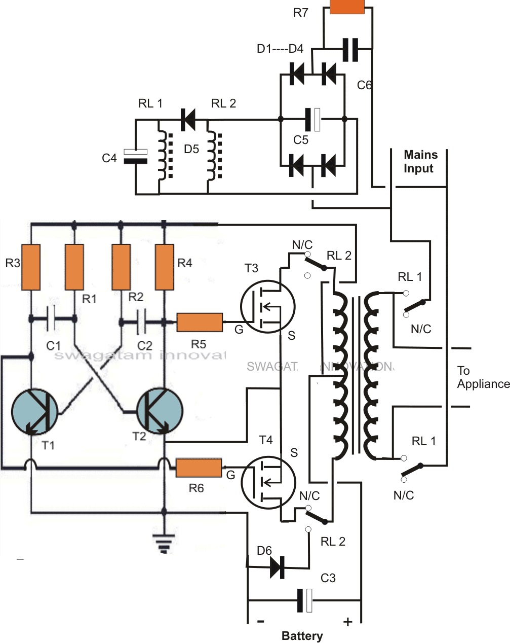
3 Cfl Ups Inverter Circuit Diagram Pdf. Predefined limits the UPS utilizes its inverter to draw current from the battery and also disconnects the AC input supply to prevent backfeed from the inverter to the utility. Flux linkage in stationary d-axis s q.

It is for a project I am planning to do. The UPS stays on battery power until the AC input returns to normal tolerances or the battery runs out of power whichever happens first. The UPS shall be capable of supplying a 135 Pn load for one minute and a 150 Pn load for 30 seconds.
The internet is flooded with single phase inverter circuit diagrams but there are only few circuit diagrams of 3 phase inverter out there a simplest possible 3 phase inverter is described here.
500 Ohm potentiometer is there which will be used to adjust the voltage to desired value. UPS which stands for uninterruptible power supply are inverters designed to provide a seamless AC mains power to a connected load without a slightest bit of interruption regardless of sudden power failures or fluctuation or even a. Flux linkage in stationary q-axis 0 Permeability of the vacuum r. 100w Inverter Circuit Simple.