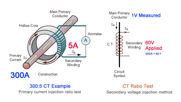
11 5kv Current Transformer Wiring Diagram. A wiring diagram is a streamlined traditional pictorial depiction of an electrical circuit. Diagram of user system for connection and MV switchgear 37 61 Diagram of the user installation 40 62MV switchgear solutions 42 7.

E-Rated fuse of 100 amps and below must melt in 300 seconds at an RMS current within the range of 200 to 240 of the fuses nameplate current rating. A wiring diagram is a streamlined traditional pictorial depiction of an electrical circuit. It reveals the elements of the circuit as streamlined shapes and the power as well as signal connections between the tools.
It reveals the elements of the circuit as streamlined shapes and the power as well as signal connections between the tools.
Current transformer secondary wiring shall be SIS type 12 AWG 65 strand extra flexible stranded copper or larger. If you want to find the other picture or article about 5kva Transformer Wiring. TRANSFORMER MARKINGS AND POLARITY Lesson 11_et332bpptx 3 Dot Notation - Terminals marked with a dot are considered instantaneously positive A B E AB - - N 1 N 2 I 1 I 2 0 degree shift C D Above Terminals A and C are positive at the same time E AB E CD 0 degrees Phasor Diagram TRANSFORMER MARKINGS AND POLARITY Lesson 11_et332bpptx 4 A B. A wiring diagram is a straightforward visual representation with the physical connections and physical layout of an electrical system or circuit.